Designing digital to analog converter (DAC) and Analog to digital converter (ADC) using Cadence
For the 10-bit current steering DAC, it is necessary to create the corresponding digital code. To do this, first, a sinusoidal signal was created with the help of MATLAB software. Then it was sampled and quantized, and finally, it was converted into binary values. Separate files were used as vpwl input.
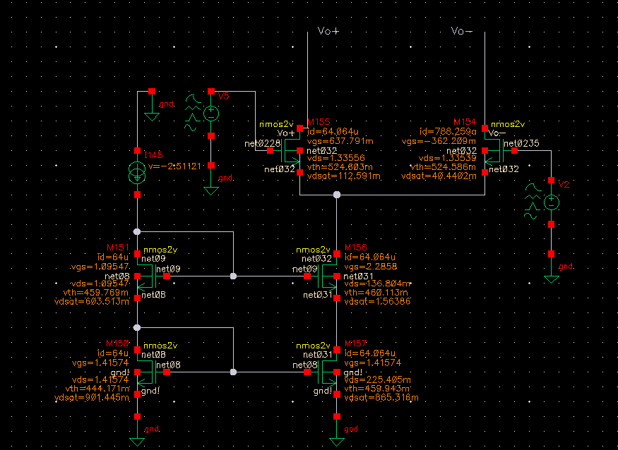
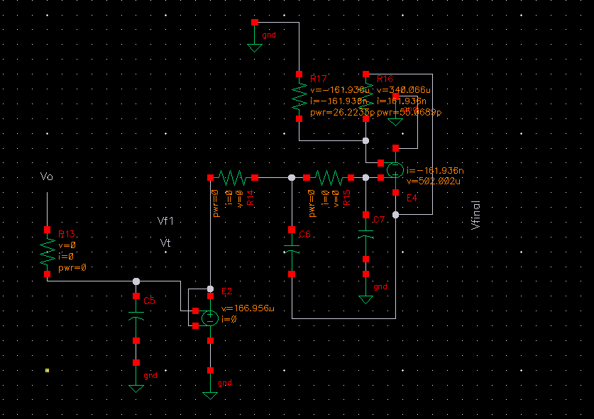
The current source and the reconstructed filter schematics are shown below:

Schematic

Schematic
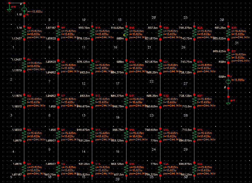
For the 5-bit Flash ADC, to create different voltages, a resistor ladder was used as depicted below:

Resistor ladder
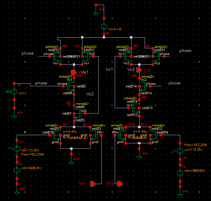
To compare voltages, a comparator circuit was designed:

Comparator circuit